Why Getting Your 40/60 Pressure Switch Wiring Right Matters
A 40/60 pressure switch wiring diagram shows exactly how to connect your well pump to its power source, and getting it wrong can damage your pump, trip breakers, or create a serious shock hazard.
Here’s the quick answer most homeowners need:
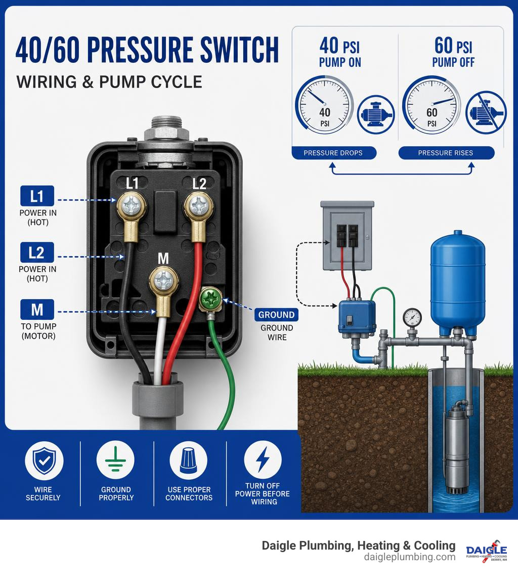
| Terminal | What Connects Here |
|---|---|
| L1 / L2 (outside posts) | Incoming power from breaker (two hot wires) |
| M / T terminals (middle posts) | Pump motor wires (from control box or pump cable) |
| Ground screw (green) | Bare copper or green ground wire from both sides |
The pump turns ON at 40 PSI and OFF at 60 PSI. The switch does this automatically by opening and closing its electrical contacts based on water pressure.
Most 220V/230V well pump systems in New Hampshire follow this same basic layout, but the details matter. Wire gauge, breaker size, control box placement, and proper grounding can all make the difference between a system that runs safely for years and one that fails on the coldest night of January.
This guide walks you through every step, from reading the wiring diagram to testing your first pump cycle.
At Daigle Plumbing, Heating & Cooling, our team has handled countless well pump repairs and installations, including the precise wiring work a 40/60 pressure switch wiring diagram requires. Let’s make sure your system is wired safely and correctly the first time.
What a 40/60 Pressure Switch Does in a Well Pump System
A 40/60 pressure switch is the automatic “on/off brain” for many residential well pump systems. It senses water pressure in the plumbing system and controls power to the pump.
When pressure drops to 40 PSI, the switch closes its electrical contacts and sends power to the pump. When pressure rises to 60 PSI, the switch opens the contacts and stops the pump.
Inside a typical mechanical pressure switch, a diaphragm responds to water pressure. As pressure changes, the diaphragm pushes against springs and a set of electrical contacts. Those springs determine the cut-in and cut-out pressures.
In simple terms:
- 40 PSI = pump starts
- 60 PSI = pump stops
- The 20 PSI difference is the normal operating range
- The pressure tank stores pressurized water so the pump does not start every time you open a faucet
That last point matters. A pressure switch should almost always work with a properly sized pressure tank. Without enough stored water, the pump may cycle rapidly, which is hard on motors, contacts, wiring, and everyone’s patience.
How the 40/60 pressure cycle works
Here is the normal 40/60 well pump cycle:
- You open a faucet, shower, hose bib, or appliance valve.
- Water leaves the pressure tank and system pressure starts dropping.
- At 40 PSI, the pressure switch closes.
- Power flows through the switch to the pump or pump control box.
- The pump runs and refills the pressure tank.
- At 60 PSI, the pressure switch opens.
- Power to the pump stops until pressure drops again.
A pressure gauge near the tank tee is the best way to confirm this cycle. Do not adjust a switch by guessing. The gauge tells you when the pump actually starts and stops.
If the pump clicks on and off every few seconds, that is not normal cycling. That is short cycling, and it can point to a waterlogged tank, low air charge, clogged pressure switch nipple, failed check valve, or incorrect tank sizing.
Pressure tank systems vs direct pressurized systems
Most homes in Derry, Salem, Manchester, Nashua, Auburn, Hampstead, Merrimack, Bedford, Windham, Hooksett, Hudson, and Londonderry use a pressure tank with the well pump system.
A pressure tank does three important jobs:
- Stores water under pressure
- Reduces how often the pump starts
- Helps maintain steady pressure at fixtures
For a 40/60 switch, the pressure tank air pre-charge is typically set to 38 PSI when the tank is empty of water. That is 2 PSI below the cut-in pressure. If the tank is still full of water when you test it, the reading will be wrong.
A direct pressurized system, such as some irrigation setups, may use valves and controls differently. But for a household well system, skipping the pressure tank is usually asking the pump to do too much work. Pumps like steady starts, not “panic mode every time someone rinses a spoon.”
If you are not sure whether your tank is large enough, start with our guide: Learn to Properly Size a Well Pressure Tank.
The 40/60 Pressure Switch Wiring Diagram: Terminals, Wires, and Safety Basics

Most residential 40/60 well pressure switches use a simple line-load layout. The labels may vary slightly by manufacturer, but the idea is the same.
Common terminal labels include:
| Label | Meaning | Typical Connection |
|---|---|---|
| L1 | Line 1 | Incoming power from breaker |
| L2 | Line 2 | Incoming power from breaker |
| M1 or T1 | Motor/load 1 | Pump motor or control box lead |
| M2 or T2 | Motor/load 2 | Pump motor or control box lead |
| Green screw | Ground | Equipment grounding conductors |
Many 230V pressure switches are double-pole switches, meaning they open and close both hot legs at the same time. That is why you usually see two line terminals and two motor terminals.
Some switches place the incoming power on the outside posts and the motor wires on the middle posts. Others are clearly marked under the cover. Always follow the diagram inside the switch cover or the manufacturer’s instructions.
For additional manufacturer-style installation guidance, see this pressure switch manufacturer installation guidance.
How to read a 40/60 pressure switch wiring diagram before touching wires
Before touching anything, look for three paths on the diagram:
-
Incoming power path
This is the line side. On a 230V pump, it is usually two hot wires from a 2-pole breaker. -
Pump or control box path
This is the load side. These wires leave the pressure switch and go to the pump motor, jet pump, or submersible pump control box. -
Ground path
Grounds do not pass through the switch contacts. They bond to the green screw, metal case, control box, and pump equipment ground.
Typical 230V color coding may include black and red as the two hot wires. In some older or field-wired systems, a white wire may be re-identified and used as a hot conductor. Do not assume color alone proves what a wire does. Use a meter and trace the cable.
A basic 40/60 pressure switch wiring diagram is usually read like this:
- Breaker hot leg 1 to L1
- Breaker hot leg 2 to L2
- Pump/control box lead 1 to M1 or T1
- Pump/control box lead 2 to M2 or T2
- All grounds to the green ground screw or grounding bar
Identifying power supply wires vs pump motor wires
The most common homeowner mistake is mixing up the breaker wires and the pump wires.
Here is how to tell them apart:
- Power supply wires come from the electrical panel, disconnect, or sometimes a properly rated outlet.
- Pump motor wires go toward the well, jet pump, or control box.
- Submersible pump cable often disappears into the well casing or conduit.
- Jet pump leads usually run directly to an above-ground pump motor.
- A control box, if present, is usually mounted near the tank, wall, or well equipment.
Before removing an old switch, take clear photos from multiple angles. Label each cable with tape:
- “LINE – from breaker”
- “LOAD – to pump/control box”
- “GROUND”
Then verify with a multimeter after the breaker is safely turned off and locked out. If you cannot confidently identify the wires, stop and call a licensed professional. Guessing is not troubleshooting. It is gambling with copper.
Safety precautions and code requirements
Electrical work around water deserves extra caution. We strongly recommend having well pump wiring handled by licensed and insured professionals, especially for 230V systems.
Before wiring a pressure switch:
- Turn off the breaker feeding the well pump.
- Lock out or tag the breaker so no one turns it back on.
- Verify power is off with a non-contact tester.
- Confirm zero voltage with a multimeter.
- Work in a dry area.
- Do not touch wiring while standing in water.
- Use properly rated wire, conduit, fittings, and strain reliefs.
- Match breaker size and wire gauge to the pump nameplate and local electrical code.
- Keep all connections tight, clean, and protected inside approved enclosures.
- Replace corroded terminals or damaged cable.
- Do not bypass overloads, control boxes, safety devices, or grounding.
- Follow the National Electrical Code and any local requirements enforced in your New Hampshire community.
- Use GFCI protection where required by current code and application.
- Call a licensed electrician or well pump professional if anything looks questionable.
Also check the pressure switch’s rating. The switch must be rated for the pump voltage, horsepower, and current. Some pressure switches are rated for both 115V and 230V, but that does not mean every pump, breaker, or wire configuration is interchangeable.
Step-by-Step: Wiring a 220V/230V Well Pump Pressure Switch
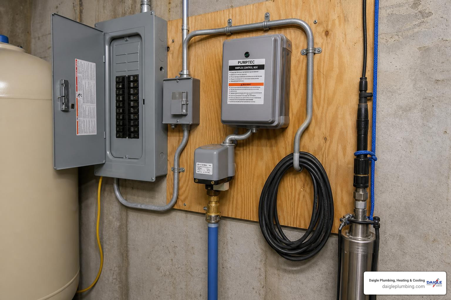
The following steps describe a common 220V/230V residential well pump pressure switch setup. Your actual system may vary, especially if you have a 3-wire submersible pump with a control box, an older jet pump, or special controls.
If the diagram inside your switch cover differs from this guide, follow the manufacturer’s diagram.
Step 1: Shut off power and open the switch safely
Start at the electrical panel.
- Turn off the 2-pole breaker for the well pump.
- Lock or tag the breaker if possible.
- Test at the pressure switch with a non-contact voltage tester.
- Remove the pressure switch cover.
- Confirm zero voltage across L1 and L2 with a multimeter.
- Check each hot leg to ground.
- Inspect the switch for burned contacts, corrosion, insect nests, or loose terminals.
- Take a photo before moving wires.
If you see melted insulation, blackened terminals, or water inside the switch, do not reuse it. Replace the damaged parts and find out why it happened.
Step 2: Connect breaker power to L1 and L2
On most 230V systems, the incoming breaker cable has two hot conductors and one equipment grounding conductor.
Connect:
- Hot wire 1 from breaker to L1
- Hot wire 2 from breaker to L2
- Ground wire to the green ground screw
Most 230V well pumps do not use a neutral at the pressure switch. They use two hot legs. If you find a white conductor being used as a hot leg, it should be properly re-identified according to code.
Make sure the copper is clean and fully under the terminal clamp. Tighten the screw securely, but do not crush the conductor. No loose strands should stick out. Loose terminals create heat, and heat creates expensive service calls.
Step 3: Connect pump motor wires to M or T terminals
Next, connect the load side.
Depending on the switch, the pump terminals may be marked:
- M1 and M2
- T1 and T2
- Motor
- Load
Connect:
- Pump/control box lead 1 to M1 or T1
- Pump/control box lead 2 to M2 or T2
- Pump/control box ground to the ground screw or grounding point
On many common 40/60 switches, the two middle posts are the motor/load terminals and the two outside posts are the line terminals. However, do not rely only on “middle” and “outside.” Use the actual labels.
If you are wiring a jet pump, these load wires usually go directly to the motor terminal board. If you are wiring a submersible system, they may go to a control box first.
Step 4: Wire the starter or control box correctly on a submersible system
This is where many submersible well pump systems differ.
A 2-wire submersible pump usually has the starting components built into the pump motor. In that setup, power often runs:
Breaker -> Pressure switch -> Pump cable -> Pump
A 3-wire submersible pump uses an above-ground control box. The control box may contain a start capacitor, relay, and overload protection. In that setup, power usually runs:
Breaker -> Pressure switch -> Control box -> Pump
The pressure switch controls when power is sent to the control box. The control box then handles the motor’s start and run wiring.
Always match the control box to the pump horsepower, voltage, phase, and manufacturer requirements. Do not bypass the control box on a 3-wire submersible pump. That control box is not decoration. It is doing important motor-starting work.
Also confirm that the pressure switch is rated for the pump horsepower. If the pump load exceeds the switch rating, a magnetic contactor or properly rated control panel may be needed.
Step 5: Ground the power source, switch, control box, and pump motor
Grounding is not optional.
Every equipment grounding conductor should be bonded together so fault current has a safe path back to the source. That includes:
- Ground from the breaker panel
- Ground to the pressure switch metal case or green screw
- Ground to the control box, if present
- Ground to the pump motor cable
- Grounding/bonding required by code for metal piping or equipment
Never use the ground wire as a neutral. Never cut off the ground because “the pump still runs without it.” A system can appear to work and still be unsafe.
After wiring, a continuity test can help verify that metal enclosures and equipment grounds are bonded correctly.
Step 6: Restore power and test the pump cycle
Once all connections are secure:
- Reinstall the pressure switch cover.
- Make sure the area is dry.
- Turn the breaker back on.
- Watch the pressure gauge.
- Open a faucet to draw pressure down.
- Confirm the pump starts at about 40 PSI.
- Close the faucet and let the pump build pressure.
- Confirm the pump stops at about 60 PSI.
- Check for leaks at the tank tee, pressure switch nipple, and fittings.
- Run one more cycle to confirm repeatable operation.
Adjusting Settings, Comparing Pump Types, and Fixing Common Problems
Wiring gets the pump powered correctly. Adjustment gets it cycling correctly.
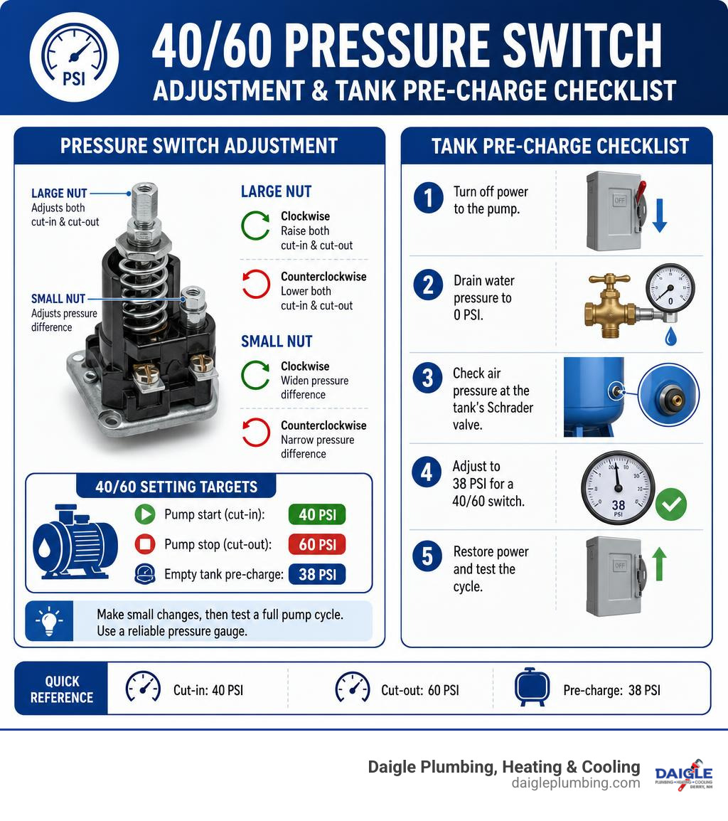
Most 40/60 mechanical switches have two spring-loaded adjustment nuts:
- Large nut: raises or lowers both cut-in and cut-out together
- Small nut: changes the differential between cut-in and cut-out
For a standard 40/60 setup, the differential is usually 20 PSI.
How to adjust a 40/60 pressure switch accurately
Use a reliable pressure gauge. Do not adjust only by counting turns.
General adjustment rules:
- Turn the large nut clockwise to raise both cut-in and cut-out.
- Turn the large nut counterclockwise to lower both cut-in and cut-out.
- Turn the small nut clockwise to widen the pressure difference.
- Turn the small nut counterclockwise to narrow the pressure difference.
Make small changes, then test a full pump cycle. Some switch documentation recommends measuring the spring nut position before changing anything so you can return to the original setting if needed.
For a 40/60 switch:
- Pump should start near 40 PSI.
- Pump should stop near 60 PSI.
- Empty tank pre-charge should be about 38 PSI.
To check tank pre-charge:
- Turn off power to the pump.
- Drain water pressure to 0 PSI.
- Check air pressure at the tank’s Schrader valve.
- Adjust to 38 PSI for a 40/60 switch.
- Restore power and test the cycle.
For a deeper walkthrough, see our guide to Adjust Well Pump Pressure Switch.
110V vs 220V pumps and jet pumps vs submersible pumps
Different pump types can use similar pressure switches, but the wiring details are not identical.
| System Type | Typical Power | Neutral Used? | Control Box? | Where Pump Is Located | Key Wiring Note |
|---|---|---|---|---|---|
| 110V/115V pump | 120V | Usually yes | Usually no | Often above ground | Hot and neutral must be landed correctly per diagram |
| 220V/230V pump | 240V | Usually no | Sometimes | Above ground or down well | Two hot legs switch through L1/L2 and M/T |
| Jet pump | 115V or 230V | Depends on voltage | Usually no | Above ground | Motor voltage setting must match supply |
| 2-wire submersible | Usually 230V | Usually no | No external box | In the well | Starting components are built into pump |
| 3-wire submersible | Usually 230V | Usually no | Yes | In the well | Pressure switch feeds control box, control box feeds pump |
The pump nameplate is the authority. It tells you voltage, horsepower, phase, amperage, and wiring requirements. If the pump is dual-voltage, the motor must be configured for the voltage supplied. A 115V/230V-capable pump wired for the wrong voltage can hum, trip the breaker, fail to start, or burn out.
Common wiring mistakes to avoid
The most common pressure switch wiring problems we see include:
- Reversing line and load terminals
- Assuming wire color without testing
- Leaving terminal screws loose
- Failing to bond grounds
- Using the wrong breaker size
- Using undersized wire for the pump load or distance
- Leaving out conduit, clamps, or strain relief
- Letting cable enter the switch where water can follow it in
- Reusing burned or corroded contacts
- Mixing 115V and 230V wiring assumptions
- Bypassing a required submersible pump control box
- Setting tank pre-charge too high or too low
- Installing the pressure switch on a clogged nipple
- Forgetting to reinstall the pressure switch cover
A pressure switch is small, but it is handling a real motor load. Treat every connection like it matters, because it does.
Troubleshooting after wiring
If the pump does not behave after wiring, use symptoms to narrow the problem.
| Symptom | Possible Causes |
|---|---|
| Pump will not start | No power, bad breaker, open pressure switch, bad control box, failed pump, loose wire |
| Pump will not stop | Incorrect adjustment, clogged pressure switch nipple, leak, bad switch, pump cannot reach 60 PSI |
| Pressure will not build | Low well yield, failed pump, broken drop pipe, clogged filter, bad check valve, leak |
| Short cycling | Low tank air charge, waterlogged tank, undersized tank, clogged nipple, bad switch |
| Breaker trips | Shorted wire, failed motor, wrong voltage, bad capacitor, locked pump |
| Contacts burn quickly | Loose terminals, excessive amperage, wrong switch rating, rapid cycling |
Short cycling is especially important because it can destroy a pump over time. If your pump turns on and off rapidly, read our guide to Well Pump Short Cycling Causes and Solutions.
If the tank seems to have lost its air cushion, our article on Waterlogged Pressure Tank Troubleshooting Fixes Prevention explains what to check next.
Frequently Asked Questions About 40/60 Pressure Switch Wiring
What does a 40/60 pressure switch wiring diagram show?
A 40/60 pressure switch wiring diagram shows the terminal layout and wire paths for the well pump circuit. It identifies where incoming power connects, where pump or control box wires connect, and where grounds should be bonded.
Most diagrams show:
- L1 and L2 for incoming power
- M or T terminals for motor/load wires
- A green ground screw
- The pressure switch contacts
- The 40 PSI cut-in and 60 PSI cut-out function
The wiring diagram does not replace the pump nameplate, breaker requirements, or local code. It is one part of the full installation.
Can I wire a 40/60 switch for either 110V or 220V?
Many well pump pressure switches can be used on either 115V or 230V systems if the switch is rated for that voltage and motor load. But the wiring is different.
On a 230V pump, you typically have:
- Two hot wires
- No neutral at the switch
- A 2-pole breaker
- Both hot legs switched through the pressure switch
On a 115V pump, you typically have:
- One hot wire
- One neutral wire
- One equipment ground
- A motor configured for 115V
Some 115V systems switch only the hot conductor, while others use a 2-pole pressure switch layout according to the manufacturer’s diagram. Always follow the switch diagram, pump nameplate, and electrical code.
Why does the pump short cycle after installing a new pressure switch?
Short cycling after a new switch installation usually means the pressure switch was not the only issue.
Common causes include:
- Pressure tank air charge is too low.
- Pressure tank bladder has failed.
- Tank is waterlogged.
- Tank is too small for the pump.
- Pressure switch nipple is clogged.
- Switch differential is misadjusted.
- Check valve is leaking.
- Pump is oversized for the system.
- There is a hidden plumbing leak.
For a 40/60 switch, start by checking the tank pre-charge. With power off and water drained to 0 PSI, the tank should usually read 38 PSI. If water comes out of the air valve, the bladder has likely failed.
Conclusion
Wiring a 40/60 well pump pressure switch comes down to four big things:
- Put incoming power on L1 and L2.
- Put pump or control box wires on the M or T load terminals.
- Bond every ground properly.
- Confirm the pump starts near 40 PSI and stops near 60 PSI.
For a standard 40/60 system, remember to set the empty pressure tank pre-charge to about 38 PSI. Also make sure the pressure switch, breaker, wire gauge, control box, and pump nameplate all agree with each other. When they do not, the pump usually tells you – sometimes by tripping the breaker, sometimes by refusing to run, and sometimes by choosing the worst possible time to quit.
If you are in Derry, Salem, Manchester, Nashua, Auburn, Hampstead, Merrimack, Bedford, Windham, Hooksett, Hudson, Londonderry, or nearby New Hampshire communities, we can help. Daigle Plumbing, Heating & Cooling is family-owned, licensed and insured, and backed by 40+ years of experience. We also offer a satisfaction guarantee, specials, and financing options.
Need safe well pump wiring, pressure switch replacement, tank troubleshooting, or a full system upgrade? Contact our plumbing professionals and schedule well pump installation or repair in Derry, NH, and we will help you wire it right.